Content found in this wiki may not reflect official Church information. See Terms of Use for more information.
Wireless Best Practices
> Meetinghouse Technology > Meetinghouse Networking
Poor wireless access point (AP or WAP) installation can degrade the speed and performance of the wireless network. Below are some “best practices” to consider when installing a wireless network in a building. It is understood that not all buildings are the same and the recommendations below may not be practical in all buildings.
Mounting Considerations
Mounting APs to the ceiling where they are visible and the wires run above the ceiling is preferred (see diagram 1). If APs cannot be installed in this manner due to security or other considerations, mount APs above the ceiling in the attic space facing down (see diagram 2). Do not mount APs on top of a desk, shelf, or similar type of surface.
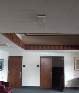
Diagram 1: Ceiling Mounted Example
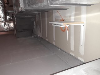
Diagram 2: Attic Mounted Example
Three primary factors impact the number of APs required within a meetinghouse:
- Building Material—Dense building material, such as brick and concrete, will impede the wireless signal more than materials such as drywall. Buildings with thicker internal building materials may require more APs to provide sufficient wireless coverage.
- Building Size—The larger the area requiring wireless coverage, the more APs will be needed. APs have a limited coverage area that is decreased by environmental conditions such as building materials, as noted above. The farther away a device is from an AP, the slower the connection will be between the device and the AP.
- Devices—The number of devices connected to a single AP and the type of traffic generated by those devices will greatly impact wireless performance. Members should be encouraged to use the wireless network only for Church purposes and to disconnect from the network when they are not using it. To optimize performance, APs should be installed in or near rooms that will have the most devices connected to the wireless network.
Other mounting recommendations and considerations include mounting APs in the following areas:
- In areas free from physical barriers such as metal structures, pipes, beams, air conditioning ducts, and so forth.
- As noted above, when mounting near ductwork or metal structures, mount the APs so they are facing down, away from the ductwork.
- Inside offices or classrooms where possible, as opposed to hallways.
- The Meraki MR33 will increase power and extend its range when there aren’t other APs nearby. By placing APs so they are not in direct line of sight in hallways, it forces the AP to power up to find the next closest AP. If APs are run only in hallways, they will see each other too easily and will power down their coverage.
- Near principle teaching and administrative areas, such as Relief Society rooms, elders quorum rooms, and bishop's and clerk’s offices.
- At least 10 feet (3 meters) from signal-emitting devices, such as microwaves, fluorescent lights, electric fans, cordless phones, and building automation equipment.
- These devices emit a wireless signal that can degrade AP performance.
- In clean, climate-controlled locations to increase the operational life of the APs.
- Less than 300 feet (91 meters) from a network switch or firewall.
- In locations that are accessible for future troubleshooting and support.
- Away from the exterior walls of the building to increase coverage within the building.
- Note that the MR33 emits a spherical pattern, connecting with devices in all directions. Take this into account when making decisions about placement locations.
- At standard ceiling levels of 10 feet (3 meters).
- Placing APs in vaulted ceilings makes them less effective because of extreme distances to connecting devices and makes them difficult to access for future troubleshooting and support.
NOTE: If physical security is an issue, mount the AP in a location that is not visible from the outside of the building.
Also, when the ISP modem has APs built in, be sure the modem AP is turned off, as it can create instability in the system.
Wireless is also impacted by the rest of the network infrastructure, such as the firewall, switches, and cabling. For current network infrastructure standards, visit the “Networking Hardware” section of Meetinghouse Tech.
Example AP Placement
Below are general guidelines for how much area a single AP can support, based on two different wall material types: (Updated Nov 20, 2025 to match current hardware specs)
| Material | Square Feet | Meters |
| Cinder Block Wall | 2,092 ft² | 194 m² |
| Drywall | 2,187 ft² | 203 m² |
Examples of wireless heat maps showing AP placements are provided below. Green circles indicate approximate AP installation locations. For each building design selected, a base and expanded wireless coverage example has been provided.
- Base Coverage: Provides minimal coverage required per building design to be usable in all parts of the building. If usage is high, areas of the building with minimal coverage may become unusable.
- Expanded Coverage: Provides increased wireless capacity throughout the building. This may be used when minimal coverage has proven insufficient in the past.
Carter Building Design with Cinder Block Walls
Base Coverage ~ 4,488ft²/417m² per wireless access point

Expanded Coverage ~ 3,595ft²/334m² per wireless access point
Fairmont Building Design with Cinder Block Walls

Base Coverage ~ 4,542ft²/422m² per wireless access point

Expanded Coverage ~ 3,767ft²/350m² per wireless access point
Cody Building Design with Drywall
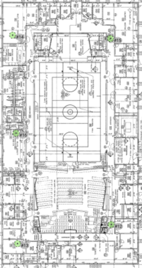
Base Coverage ~ 5,113ft²/475m² per wireless access point
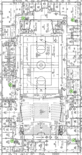
Expanded Coverage ~ 4,251ft²/395m² per wireless access point
Sage Building Design with Drywall

Base Coverage ~ 5,242ft²/487m² per wireless access point

Expanded Coverage ~ 3,928ft²/365m² per wireless access point
Legacy Building Design with Drywall

Base Coverage ~ 4,768ft²/443m² per wireless access point
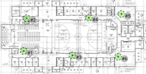
Expanded Coverage ~ 3,971ft²/369m² per wireless access point
